Looks liike a few others have had this problem. How ever mine seams to be a bit different then what they have had. I am trying to use the PSU Control to turn on an off my Wanhao I3. I am using The GPIO (board) pins 2, 4, 6. I am using this 5v relay board. https://de.aliexpress.com/item/5V-Relay-Module-1-Channel-Low-level-for-SCM-Household-Appliance-Control-FREE-SHIPPING-for-arduino/32315027365.html?src=google&albslr=221442105&albch=shopping&acnt=708-803-3821&isdl=y&aff_short_key=UneMJZVf&albcp=653153647&albag=34728528644&slnk=&trgt=61865531738&plac=&crea=en32315027365&netw=s&device=c&mtctp=&albbt=Google_7_shopping&aff_platform=google&gclid=CjwKCAjwh9_bBRA_EiwApObaOAe_vrGjWWseGbwv5uJ2uZvszIQlHgOIK5N4Vl2QIMZ2S_qklbbBZRoCmmYQAvD_BwE&gclsrc=aw.ds So with it plugged in the the Pi the red light comes on. Once I set it to GPIO (board) pin 8 the green light on the relay board turns green. Now when I use the lighting bolt at the top to try and turn the relay on or off nothing happens on the relay end but the lighting bolt with go from green to gray with nothing happening. I have tryed every thing I can think of. Last night I even did a fresh install of octo print with only installing PSU control plug in to make sure it was not a conflicting plug in. Any Ideas on what is going on. I am using the newest Pi out 3 b+.
For me it works fine. I’m using a keyestudio relay board that is plug and play to PI 3.
My setup works 2 ways. First, setting GPIO Mode to BCM, Switching Method GPIO PIN, Sensing method internal.
Did you try to turn on and off your relay using a script? This is the way I was doing before. Created a bash script, and used the plugin changing Switch Metod to System command, calling the turn-on and turn-off scripts.
Turn-on script:
#!/bin/bash
gpio export 8 out
gpio -g write 8 1
Turn-off script:
#!/bin/bash
gpio export 8 out
gpio -g write 8 0
This is a simple method, and you can add other commands, like turning off the usb port to turn off the printer display.
I do not think it is a problem with the hardware its self. And the reason I say that is because in the setting for Psu control under the switching setting when i set the gpio pin to 8 it turns on the relay and then when I change the number back to 0 the relay will turn off. So gpio pin set to 8 the relay turns on but the lighting bolt in the navbar does nothing. When its grayed out the relay is on when its green the relay is on. It just stays on as long as I have the gpio pin set in the settings.
I have seen a few video's on YouTube where the relay is hooked directly to the pi with out the addition of extra parts to work . What does adding in extra parts achieve?
The transistor just reduces the draw from the GPIO pin, so the relay doesn't destroy your RPi. It's a required component and already on most relay boards (it'll be a very small chip with 3 pins most likely).
My instinct says you've got the plugin misconfigured and it's switching the wrong pins. Just a guess, though, since you didn't show your settings.
Thanks for the reply. I will try to add a video later tonight to help clear up some things.
taratata-
are you switching the mains power on the ATX power supply?
depending on the controller you are using, there might be other ways-
This uses RAMPS native pins to control the sense wire of the ATX controller-
I beleive that you can do the same thing by using the controller to make the connection via the relay as well between the +5VFSB & PS_ON, same way we do it with a simple toggle switch.
I am using a raspberry pi and the power supply that came with my wanhao i3
Hello did you solve the problem with relay? I have de same issue and I don´t have more ideas to tray it.
Hi R1dd1ck913,
I am wondering what you mean by "GPIO (board)", Is that the relay board ? The relay board according to the picture has VCC, GND and IN, how did you hook them up to your R-Pi ?
First thing would be to have it working on the plain command line I guess.
Regards
Jan P.
This guy solved the issue with a transistor and resistor. I can confirm this works.
Thank you. Sorry to say I'm glad some one else had the same problem as me. Thanks for the link I will order some parts and try this out.
I realise this is an old post but i just want to give an alternate solution to this issue.
There are 2 issues at play here. The first is the relay's input is inverted meaning in order to turn it on the input pin must be pulled low. This alone isnt an issue because PSU Control has an option to invert the control signal. But because its a 5v relay that also means the input pin must be allowed to reach 5v in order for the relay to switch off.
And theres the second issue. The PI is a 3.3v device so as soon as a GPIO pin is set to output mode it is oulled down to 3.3 volts which seems to be enough to activate the relay.
My solution is to simply put a string of 3 diodes in series on the control line. Each diode has a voltage drop of 0.5 volts. This allows the control relay's input pin to reach 4.8 volts (3.3 + 1.5) when the GPIO pin is high. Thats high enough to turn the relay off.
This does also mean the relay input pin can only be pulled down to 1.5 volts when the GPIO pin is low but we already know thats more than low enough to turn the relay on.
tbh i probably would have just used the transistor solution if i had bothered to properly read this thread but i missed the solution and so went and figured out my own solution. The only real advantage my solution has is it can be easily spliced into your existing signal wire without needing an additional board.
In a situation like this I will first insert a large heatshrink (3" long) up on the insulated wire. Next, I will add a smaller heatshrink section (1" long) which will eventually cover all those naked diodes. You then shrink the smaller one over the diodes, bring in the bigger one and shrink it down over all the wires.
I had the same issue, and it took some time to figure it all out.
What I had : sometimes it worked just fine, sometimes there was no 'click' when the command was sent to switch the relay back to normal position (which means that the Pi is sending a low command). It was like 'low' was not low enough.
So, long story short : switching a relay DIRECTLY from the Pi's GPIO pins is NOT a good idea.
And indeed, when I switched the relay by hitting the ground contact, it really did switch. So there must have been some voltage still left, not 'low' enough to switch it.
After some digging, I found out that -in order to properly switch a relay- you need to add a transistor or opto coupler first, they make 'low' really 0 (and no voltage left), so the relay really switches nicely.
This is a very simple but very effective design (credits to the original author) : https://gpailler.github.io/2018-03-02-octoprint-psucontrol/
Hello,
I'm having the same problem but there is something I don't understand, why do I need the extra circuits when the videos on YouTube have a direct connection to the Raspberry Pi? Its because it's a diferent relay? Should I buy a diferent relay? I'm not confirtable doing the custom circuit...
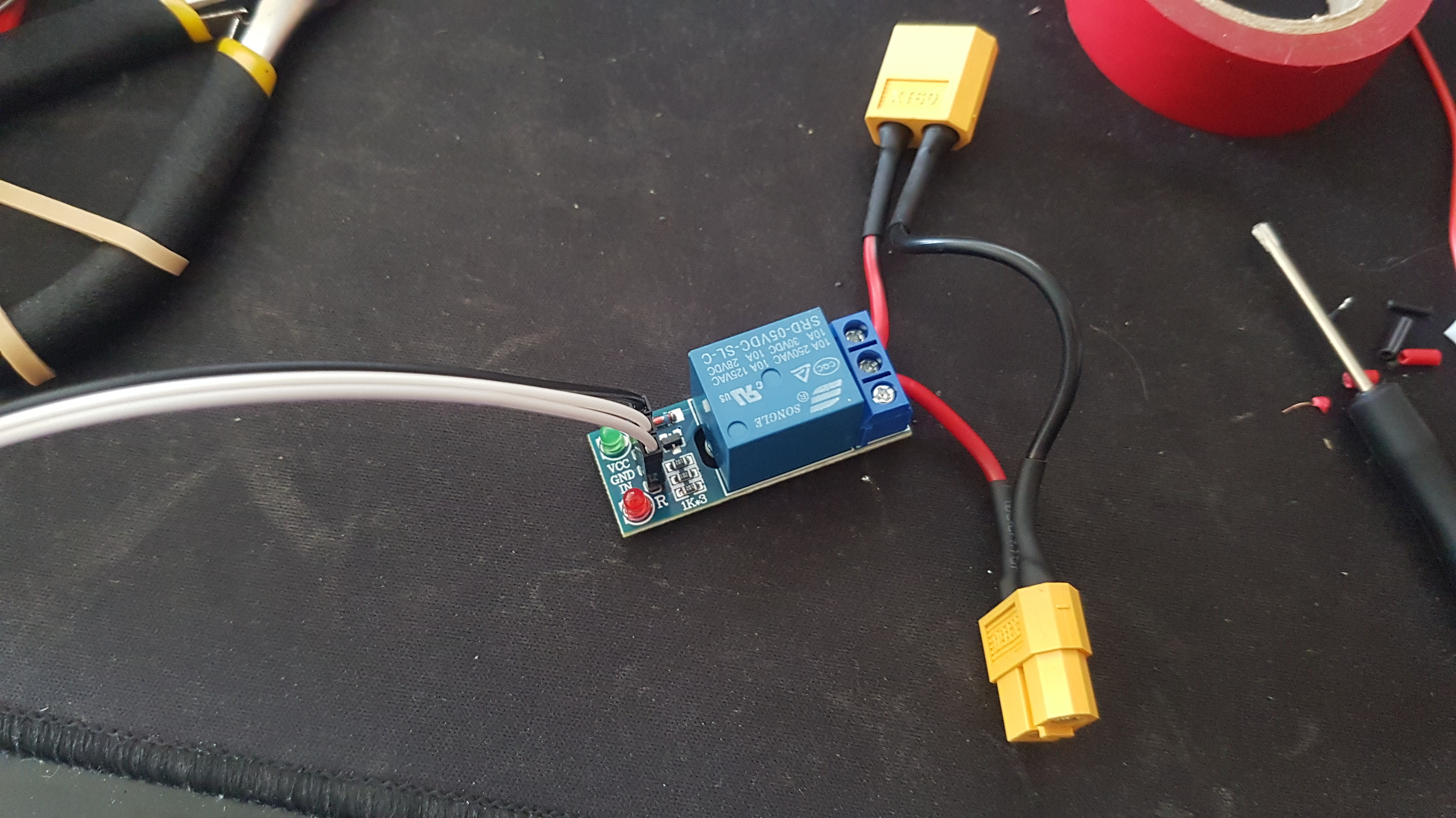
Photo of my relay attached and I'm using Raspberry Pi 3 B+
Thanks.
Hello,
Wasant he talking about the transistor, in my case, already included in the relay board?
I was talking about the extra circuit just to make it work since I have the same problem. After setting the pin number on PSU Control and save the relay activates and stays always On... Previous comments are suggesting diodes or transistors to solve the problem. I was talking about those extra circuits.
Thanks
brandon's reply a little later suggests that there are two issues: inversion and the 3.3V data logic versus a 5V relay.